Sound geotechnical decisions require knowledge of the soil and groundwater conditions. The aim of ground investigation is to provide reliable basic geotechnical data for the planned structure.
Drag the slider
Ground investigation is preparatory geotechnical work: we collect every piece of information the designer needs. The results of the desk study and of the actual ground exploration are summarised in the ground investigation report.
An appropriate foundation ensures that settlement, tilting and cracking of the superstructure can be avoided.
The cost of the investigation is a fraction of what it costs to deal with an unexplored ground problem afterwards (e.g. retrofit piling, grouting, etc.).
Knowing in advance about a high groundwater level, voids or cellars, or soft soils reduces construction risks and delays.
Before the actual exploration starts, we visit the site and collect the existing data on the area. Knowledge of the site + document research.
Based on the desk study we draw up an investigation plan: how many explorations, how deep, with which method. Then the field exploration is carried out with the chosen methods.
The aim of the desk study is to have as much relevant information as possible about the site before the actual ground exploration begins. There are two main lines: site reconnaissance and review of the available documents, maps and data. Together they ensure that the investigation plan is well prepared.
For every design task we have to go to the site and walk the surroundings. Damage to existing buildings, the vegetation, the topography and information from local residents together reveal a great deal about the expected geotechnical conditions. The interactive figure below shows six typical things to look out for.
Click a number in the picture to find out what it means geotechnically.
Local residents are a valuable source of information: it is worth asking about earlier structures, dug wells, groundwater fluctuation and flooded cellars.
Similar damage on several buildings is a clear warning that the ground is the cause. Such observations must always be documented.
In many places in Hungary there are underground cavities (cellars, mines, voids). Checking the cellar and mine registers is recommended for every design.


Geological maps allow an estimate of the geological formations expected on the site even before exploration. By age, two basic groups are distinguished (the map excerpts are in Hungarian).
Covered maps show the Quaternary (Holocene and Pleistocene) soils at the surface, i.e. the layer on which we usually found in Hungary (unless there are several basement levels).
Besides geological maps, many other, partly thematic data sources are available. Most of them cover Budapest and the larger cities in more detail, but the national maps can be used everywhere as a starting point. The examples below are original Hungarian documents.
Mainly in Budapest: made ground, buried channels and oxbows, landslide-prone areas, karst, fissure and confined water, and the sulphate content of the groundwater.

A national map with the depth of the average groundwater level. More detail for Budapest: the depth below ground of the average and the estimated maximum water level, both colour-coded.

Contours of the estimated maximum groundwater level relative to the Baltic datum, and the locations of groundwater observation wells. Still a reference today.

Managed by the Hungarian building documentation and information centre (ÉDIK): earlier reports and exploration data, digital and free of charge. A large amount of pre-1990 material.

10 questions on this chapter. The result shows which parts are worth revisiting.
After the desk study and the site reconnaissance, an investigation plan is drawn up: we decide the type, depth and number of explorations. Then the field exploration is carried out with the chosen methods. The methods fall into two main groups: direct and indirect explorations.
Ground explorations follow two fundamentally different logics. Direct methods physically expose the soil, while indirect methods infer its properties from the response of the ground. The two groups are usually used together, each calibrating the other.
We actually expose the soil: we see the layering, we can take samples and we measure the groundwater level directly. The basis of laboratory testing.
No direct exposure, no sampling. A rod string is pushed, driven or rotated into the ground, or a physical measurement is made at the surface, and the soil properties are inferred from the response.
Soil samples, accurate knowledge of the layer structure, direct measurement of the groundwater. The basis of laboratory testing — every site needs at least one direct exploration.
Continuous, fast data over the full depth (CPT). Cheaper than boring + sampling + laboratory together. Reliable only when calibrated against boreholes.
The two kinds of method give the best result in combination. Indirect tests must always be calibrated against laboratory test data from the boreholes.
The two main direct methods: boreholes give data with depth, while trial pits expose the layering over a large section. Choose below which one you want to review.
The modules below present the boring techniques most commonly used in Hungarian practice. Click a method for details.
Trial pits are dug by hand or with an excavator. Their advantage over boreholes is that the layering can be seen over a larger section, and undisturbed samples are easy to take. Drawback: they can only go down to the groundwater level, and at greater depth shoring or battered sides are needed.


“Scanning” the extent of fill or organic layers — an excavator can quickly dig 2–3 m pits. In cohesive, stable soil they can be dug with vertical sides.
A frequently used variant: exposing the foundation of an existing building (foundation level, footing width). Essential when adding a storey or building right next door.
The trial pit must not be placed where the planned foundations will be. The backfilled, uncompacted material may later cause settlement precisely at the pit.
Indirect methods do not open up the ground — they draw conclusions either from a physical measurement at the surface or from the penetration resistance. They provide fast, continuous data, but no samples: they do not replace boreholes, they only complement them.
Physical measurements made at the ground surface tell us about the layering, the state of the soils, the position of the groundwater and the presence of voids. They give quick results and are excellent as preliminary or supplementary information supporting the exploratory ground investigation.
Determines the conductivity of the subsurface layers from induced eddy currents. Mapping wall remains, pipelines and voids, distinguishing soil types.

Electromagnetic waves sent out by a high-frequency radar antenna are reflected from layer boundaries. Utility detection, buried objects, groundwater level, karst.

A tomographic section from the electrical resistivity measured along a line of electrodes. Aquifer exploration, dam investigation, tunnels. Investigation depths of several hundred metres are possible.

Measures the distortion of the Earth’s magnetic field with a magnetometer. Metal pipelines, cables, graves, building remains. Archaeological and geotechnical investigation.


A layer section from the reflection of artificially generated elastic waves. Measuring P- and S-wave velocities and Young’s modulus — non-destructive mechanical parameters.

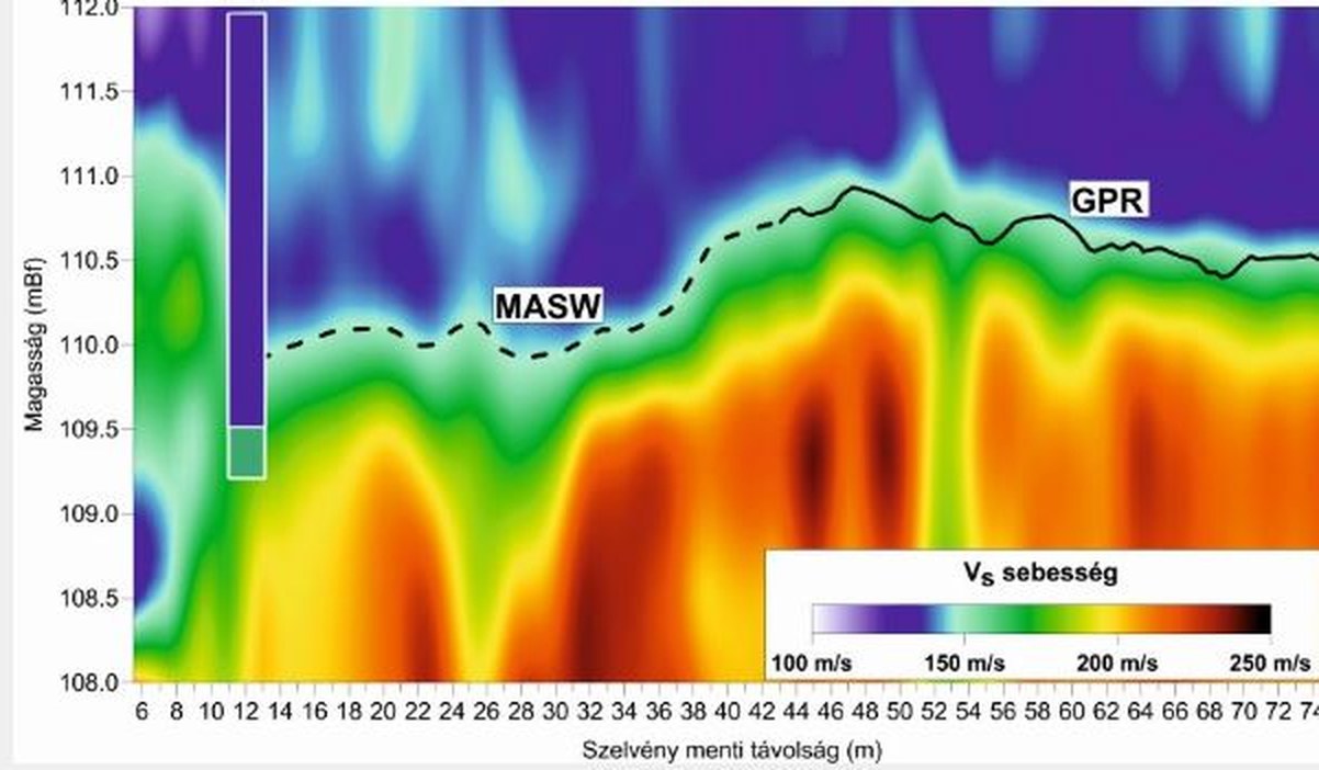
Rayleigh waves generated by a hammer blow are recorded by a geophone array; the dispersion of the waves gives the depth profile of the shear-wave velocity (vs). Ground classification (vs,30), dynamic modulus, loose and dense zones — fast and non-destructive.

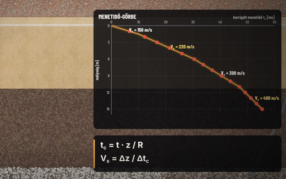
At the surface a plank is held down by a vehicle wheel; striking its ends horizontally sends out a shear wave (S). In the grouted, cased borehole a 3-component geophone, clamped to the wall every metre, records it. The arrival is read from the opposite-polarity signals of the two blow directions; the corrected travel times give vs and vp layer by layer, and from them G0 = ρ·vs2 and vs,30.

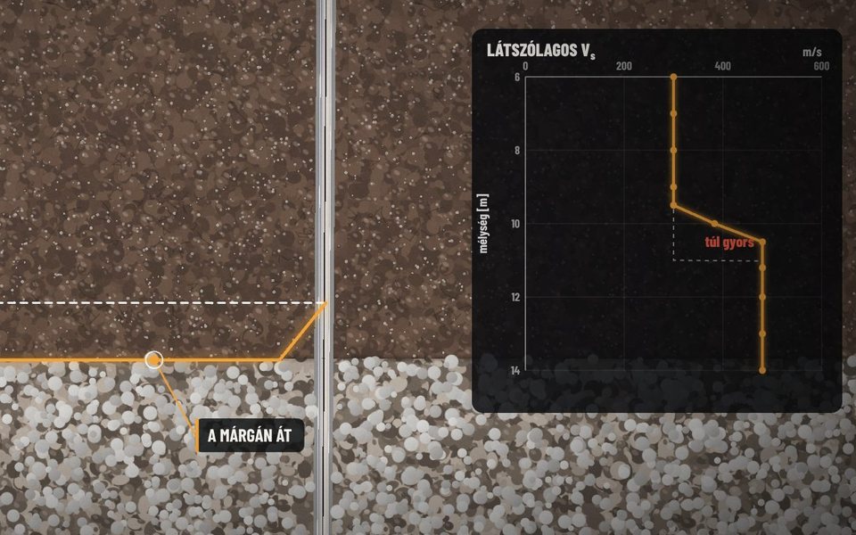
Two or three grouted boreholes in a line, 3–6 m apart. In one, a downhole hammer generates a shear wave with upward and downward blows; in the others, geophones clamped to the wall at the same depth record it. With the true distance known from inclinometer surveys, vs = (L2 − L1) / (t2 − t1); the accuracy does not deteriorate with depth, but near a stiff layer refraction must be watched for.

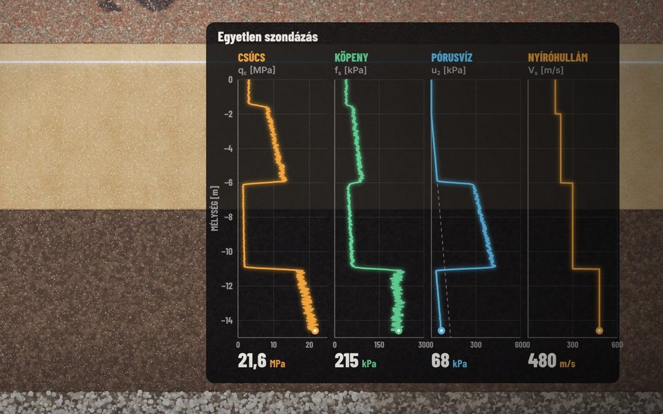
The module above the CPTu cone contains horizontal geophones. At every rod addition the push is paused and the two ends of the steel beam under the levelling foot are struck. The records at two successive depths give a pseudo-interval vs; in a single run qc, fs, u2 and vs — without a borehole, but only as deep as the cone can reach.

A rod string is pushed, driven or rotated into the ground from the surface, and the soil properties are inferred from the penetration resistance. No samples (except SPT), fast and much cheaper than boring + laboratory. Always used calibrated against borehole results.
Twenty short, captioned 3D animations on boring, sounding and geophysical methods. Click a card — the video can be watched large, or full screen. The same videos start automatically when you click the technique in the method selector, and on the geophysics cards they can be played below the description.
Soil samples are put into five quality classes according to their disturbance, and sampling methods into categories A, B and C. The range of laboratory tests depends on the quality of the sample we bring in (EN ISO 22475-1).
The soil structure is unchanged from the original. All laboratory tests can be carried out.
Very slight disturbance. All tests can be carried out with a suitable sampler.
The composition and water content are natural, but the phase state is partly disturbed.
Soil identification is possible, the natural water content can be measured.
Soil identification is possible, a Proctor test can be made and the organic content can be measured.
Sampling methods fall into three categories according to the sample quality they produce:
Note: undisturbed samples cannot be taken from cohesionless granular soils, either from boreholes or from trial pits. The density is measured in situ with separate methods (e.g. sand replacement, rubber balloon density test).


10 questions on the Ground exploration chapter.
When drawing up the investigation plan, besides choosing the types of test, the required exploration depths and the spacing of the explorations must be set. Both depend on the type and size of the planned structure, the Geotechnical Category, the design stage and the geological conditions. Recommendations are given by EN 1997-2 and by the Geotechnical Section of the Hungarian Chamber of Engineers (MMK).
The extent of the investigation also depends on the design stage. At first it may be enough to rely on existing data, but the detailed design stage already needs denser exploration, so that every geotechnical task (foundations, excavation support, dewatering) can be designed.
A preliminary ground investigation report can often be prepared without any exploration, relying only on the available archive data.
All essential geotechnical information should be known. It must be possible to decide whether shallow or deep foundations are appropriate.
The explorations are placed so densely that every geotechnical task (foundations, excavation support, dewatering, etc.) can be designed economically at detailed design level.
The extent of the investigation is influenced by the Geotechnical Category of the task. This is determined by the complexity of the ground conditions, the characteristics of the structure and the risks. There are 3 Geotechnical Categories.
The investigation plan often has to be modified on site if the layering found is not the one expected. An exploration must not be stopped in soft/organic soil, even if it was planned to end there.
Every site needs at least one direct exploration, a borehole or an open pit, with sampling for laboratory tests. Indirect tests complement it.
The required exploration depth is governed by the expected depth of influence of the stresses (zone of influence). The calculator below gives an estimate for the most common foundation types, following the relevant recommendations.
For strip and pad footings, min. 4–6 m below foundation level, but at least 3 times the footing width.
| Foundation type | Minimum exploration depth |
|---|---|
| Strip and pad footings | Below foundation level min. 4–6 m, but at least 3 times the footing width |
| Raft foundation | 0.5–1.0 times the smaller raft dimension |
| Single pile foundation | 5 times the pile diameter below the pile toe |
| Wide excavation | Below its base, min. 0.4 times the excavation depth, but min. 2 m |
| Narrow trench | Below the bottom min. 2 m, but at least 1.5 times the width |
Note: an exploration in soft/organic soil or fill must not be stopped, even if it would end there at the depth set in advance. Always explore down to a stable, competent layer.
The minimum spacing of the explorations depends on the design stage, the size and nature of the structure and the geological conditions. The list below gives guidance for the detailed design stage and average geological conditions.
| Type of structure | Minimum number / spacing of explorations |
|---|---|
| Smaller buildings (e.g. family house) | Min. 2–3 explorations |
| High-rise buildings, industrial structures, halls | Min. 3, at most 25–40 m apart |
| Buildings with a large footprint, industrial parks | In a grid of at most 40–60 m |
| Bridges (depending on the span) | Min. 1–2 boreholes and CPT soundings per support |
| Special structures (e.g. chimneys, wind turbines) | Min. 3 explorations, preferably one of them a CPT sounding |
Similar rules and recommendations apply to road, railway and hydraulic earthworks, utilities and tunnels.
10 questions on the Extent of investigation chapter.
The groundwater situation is decisive in many respects: choosing the foundation level, dewatering the excavation, the risk of uplift, changes in the soil’s physical properties. This chapter reviews the types of groundwater, the important water levels and how to deal with aggressive groundwater.
Groundwater affects almost every geotechnical task in design. Without a proper investigation, setting the foundation level, dewatering, the risk of uplift or the effect of water level fluctuation all become risks.
Foundation level, dewatering of the excavation, risk of uplift, groundwater damming (METRO tunnel, underground car park), hydrological balance.
Water level fluctuation directly affects the strength and compressibility of the soil. The result of the settlement calculation changes with it too.
Water abstraction, groundwater lowering, burst pipes, deforestation, opening a mine, building a fish pond or reservoir — each of them upsets the balance.
Groundwater occurs in several forms. Continuous groundwater is the water above the first impermeable layer below the surface that completely fills the pores of the soil. Its surface may be at atmospheric pressure (unconfined / free surface) or under pressure (confined).
The water above the first impermeable layer that completely fills the pores. At atmospheric pressure it is unconfined (free surface); under pressure it is confined.
Water that forms locally above an impermeable clay lens as a result of concentrated infiltration. Its extent is limited, but it may matter for design.
Typical of hilly areas. Not continuous groundwater: it “travels” towards the valley in thinner permeable (sandy) layers between impermeable ones. It can cause a risk of landslides.
Water in the cavity systems of carbonate rocks and in rock fissures. Typical where there is no continuous groundwater — e.g. the Buda Hills.
The level of continuous groundwater is never constant: because of seasonal and other effects it varies within a fluctuation range. In design several characteristic water levels are distinguished, each with a different role.
Drag the slider: the water level varies between the estimated MIN and MAX because of seasonal and other effects.
| Water level | Meaning |
|---|---|
| Water strike | The depth at which water is first observed during the investigation (in a borehole or a trial pit). |
| Rest water level | The water level that has “settled” during the investigation, once the water pressure has equalised. |
| Estimated minimum | The lowest water level expected with a 50-year return period (1-year reference, 2% probability). |
| Estimated maximum (characteristic) | The highest water level expected with a 50-year return period. This is the one we design for. |
| Design level | The estimated maximum increased by a safety margin (according to EC7, depending on the limit state). |
| Construction water level | The water level expected during construction — the basis for designing the dewatering. |
The fluctuation range (water level variation) is max. 0.5–1.0 m depending on the area, but near surface waters (rivers, lakes) it can reach 6–8 metres, because the groundwater “communicates” with the watercourse.
So far this section has dealt with continuous groundwater. But groundwater can occur in several “types” — click the tabs to see the section and the risks of each type.
If the design groundwater level reaches the structure, its chemical composition — especially the sulphate content — determines whether the concrete dissolves, swells or decomposes. The Hungarian standard MSZ 4798-1:2016 defines four exposure classes.
Table 1 of
MSZ 4798-1:2016
| Exposure class | Sulphate ion content (SO₄²⁻) | Description |
|---|---|---|
| — | < 200 mg/l | Not aggressive |
| XA1 | 200 – 600 mg/l | Slightly aggressive |
| XA2 | 600 – 3000 mg/l | Moderately aggressive |
| XA3 | 3000 – 6000 mg/l | Highly aggressive |
Moderately aggressive environment. The concrete needs extra attention: sulphate-resisting cement, higher cement content, lower w/c ratio.
The protective measures required for each exposure class are detailed in Table 1 of MSZ 4798-1:2016: required cement type, cement content, minimum concrete strength class, member thickness, concrete cover. The pH and other properties
(e.g. ammonium and magnesium ions) also matter — a full chemical analysis must always be carried out.
10 questions on the Groundwater chapter.
The geotechnical designer summarises the exploration and laboratory test results in a ground investigation report. This document contains all the data and evaluation the designers (mainly the structural and geotechnical designers) need. Below we review the structure of the report and the graphical documents that go with it.
The ground investigation report consists of two main parts. The first part presents the information collected, the second its engineering evaluation. Click the items for details.
The first basic element of the report: identifying the area investigated and the planned structure. It records the location of the plot, its access, and the type, dimensions and expected loading of the structure.
It also covers the known history: earlier structures, earlier explorations, the results of the site reconnaissance.
Based on the final investigation plan, an exploration site plan is drawn. It shows the label and position of each exploration and the lines of the planned cross-sections. The exact coordinates are given in the text of the report.
For a hall with a large footprint a 40–50 m grid is typical. The different tests (boreholes, DPH, CPT, etc.) can be made alternately, in several stages.
The site plan must show the lines of the planned cross-sections (marked e.g.
A–A', B–B', etc.). Each section connects several exploration points.
The site plan is only visual — the exact GPS coordinates and levels are recorded in the text of the ground investigation report.
The layer sequence and groundwater data observed in a borehole are recorded, together with the laboratory tests, in a borehole log. Combining several exploration points in one figure gives a cross-section — the layers are joined between the exploration points by linear interpolation.
The second main part of the ground investigation report contains the evaluation:
| Item | What it contains |
|---|---|
| Presentation of the results | A clear, evaluated summary of the test results |
| Borehole logs and cross-sections | Graphical presentation, written description of the layering |
| Groundwater conditions | Observed groundwater situation, the various water levels, aggressiveness |
| Design parameters | Mechanical and physical parameters that can be used directly in design |
10 questions on the Ground investigation report chapter.
The 50 true/false statements below cover the whole course material — there are statements from every chapter (Introduction, Desk study, Ground exploration, Extent of investigation, Groundwater, Evaluation of the results). Decide whether each statement is true or false; every answer is followed by an explanation. You get an evaluation at the end.